DX11 Renderer
The Polytree Engine features a DirectX 11-based forward renderer. The renderer is built upon the following systems:
-
Multiple vertex data layouts
-
Buffers
-
Textures
-
Sprite sheets
-
2D sprite animations
-
Bitmap fonts
-
Material pipeline
-
Programmable shading pipeline(vertex shaders, pixel shaders and compute shaders)

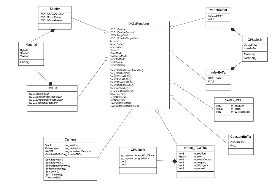
Overview of projects running on DirectX11 renderer
Class Architecture
.png)
Building and Drawing the Mesh
The system supports two types of vertices: PCU and PCUTBN. Geometric shapes are built using triangles, with each triangle consisting of three vertices. During rendering, vertex data is transferred from the CPU to the GPU for drawing. To optimize memory usage, the system provides two drawing methods:
-
Direct vertex drawing: Utilizes a straightforward vector of vertices.
-
Indexed drawing: Uses vertex indices to reuse common vertices, minimizing memory usage by avoiding duplicate vertex data.
Furthermore, the system employs vertex and index buffers to manage memory efficiently. These buffers store vertex and index data on the heap, eliminating the need to reconstruct them every frame.
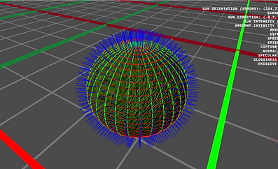
Indexed Sphere with Normal (BLUE), Tangent (RED), BiTangent (GREEN)

OBJ Model with Normal (BLUE), Tangent (RED), BiTangent (GREEN)
Textures / Spritesheets / 2D sprite animations / Bitmap fonts
The engine offers robust texture mapping capabilities for all primitive shapes, featuring UV mapping tailored to various 3D primitives. This is illustrated by the custom UV layouts for AABB3s, cylinders and spheres, where each face is systematically assigned numbered coordinates.
The UV mapping system is carefully designed to suit the geometry of each primitive shape, ensuring accurate texture wrapping with minimal distortion. The AABB3, cylinder and sphere examples, with their numbered UV layout patterns, highlight this systematic approach, enabling consistent and predictable texture mapping across all supported primitive shapes.

Test UV texture
The engine includes support for bitmap fonts, sprite sheets, and sprite animations, enabling efficient rendering of text and 2D graphics. Bitmap fonts allow for fast and customizable text display, while sprite sheets optimize memory usage by consolidating multiple sprites into a single texture. The engine's sprite animation system leverages these sheets to create smooth and efficient animations, enhancing visual performance and resource management.

Sample Spritesheet
Flamethrower using 2D sprite animations
UV Mapping for Sphere
UV Mapping for Cylinder
UV Mapping for AAB3D

Bitmap Font

2D Sprite Animation
Material pipeline
The material pipeline supports multiple texture layers to enhance rendering detail:
-
Diffuse maps provide base color and surface details, such as brick and grass textures.
-
Normal maps add surface relief and fine details, represented by blue texture maps.
-
Specular/Gloss maps control the shininess and reflectivity of surfaces.
-
Emissive maps enable surfaces to appear self-illuminated.
Each primitive shape can utilize different combinations of these texture layers, allowing for complex material compositions. This is demonstrated through examples of brick and grass materials, where multiple texture maps (diffuse, normal, and spec/gloss) combine to create realistic surface appearances.

Primitive geometry with the different texture maps
Sample Diffuse, Normal and Spec/Gloss/Emissive texture maps
Phong and Emissive shading
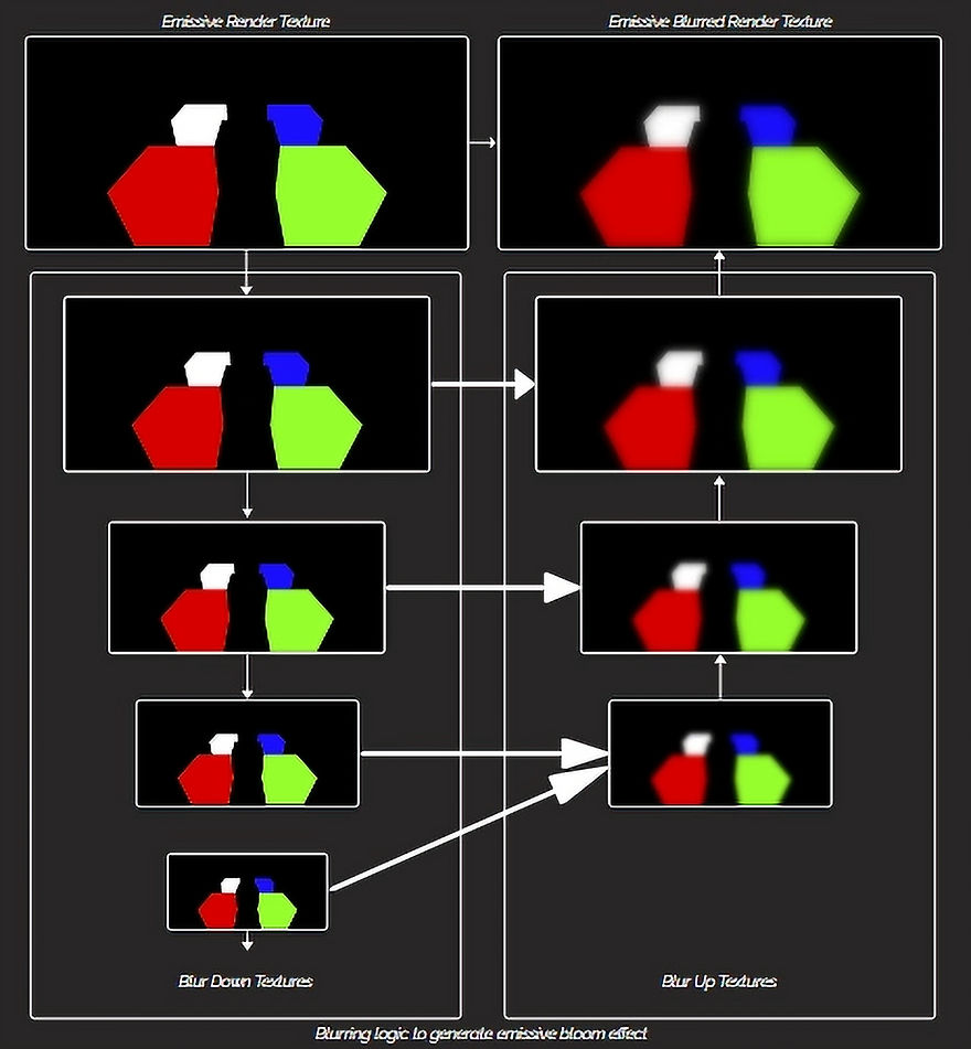
The engine features Blinn-Phong shading and emissive shading with a blur-based approach to enhance visual quality. Blinn-Phong shading provides realistic lighting by calculating ambient, diffuse, and specular components, delivering smooth highlights and detailed surface reflections. This model is well-suited for rendering materials like metals and plastics with accurate light interactions.
In addition, the engine supports emissive shading to simulate self-illuminating surfaces, such as glowing signs or energy effects. This is achieved using a blur down-and-up technique, where the emissive textures are downsampled, blurred to soften edges, and then upsampled back to the original resolution. This process creates a subtle glow effect, enhancing realism by simulating light diffusion and bloom. Combining Blinn-Phong and emissive shading allows the engine to render a diverse range of materials and lighting effects convincingly.
Emissive Shading
Phong + Emissive Shading
DX11Renderer class structure
What did I plan to accomplish?
-
Implement the DirectX11 graphics pipeline
-
Implement multiple blending modes
-
Implement multiple depth modes
-
Implement material pipeline
-
Implement basic lighting such as directional light, spot light and point lights
-
Implement complex model loading pipeline
-
Use softwares like RenderDoc to debug graphics data
What does the renderer currently feature?
-
Supports PCU(position, color, uv) and PCUTBN(position, color, uv, tangent, bitangent, normal) vertex data layouts
-
Supports alpha, additive and opaque blending
-
Supports functionality to enable and disable depth and has a x-ray depth mode
-
Supports materials (normal maps, specular maps, gloss maps)
-
Supports textured 3D model foward rendering
-
Supports directional, spot and point lights
-
Supports Phong and emissive (bloom effect) shading
Features to add to the renderer
-
Add in support for deferred rendering
-
Add in support for shadow mapping
-
Add in support for anti-aliasing(MSAA, TAA, FXAA)
-
Make the abstraction layer more elegant
-
Utilise compute pipeline instead of pixel shading to implement blurring operations
Graphics Debugging (RenderDoc)
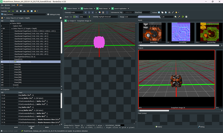
Highlighted draw call in purple
Loaded textures for the current drawcall
Current render target
GPU call stack
Test capture on RenderDoc
What I accomplished?
-
Learned how to read information being processed through every pipeline stage
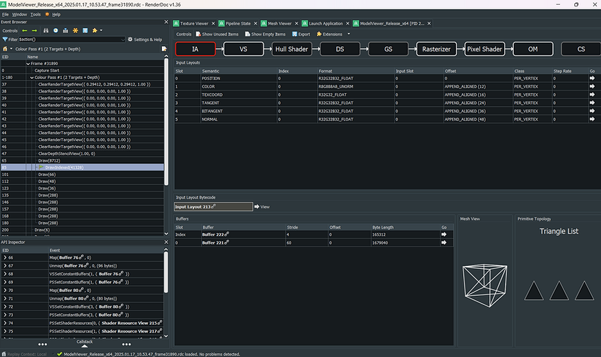
Vertex input layout
Pipeline stages (On IA stage in this example)
Input Assembler stage for the above capture
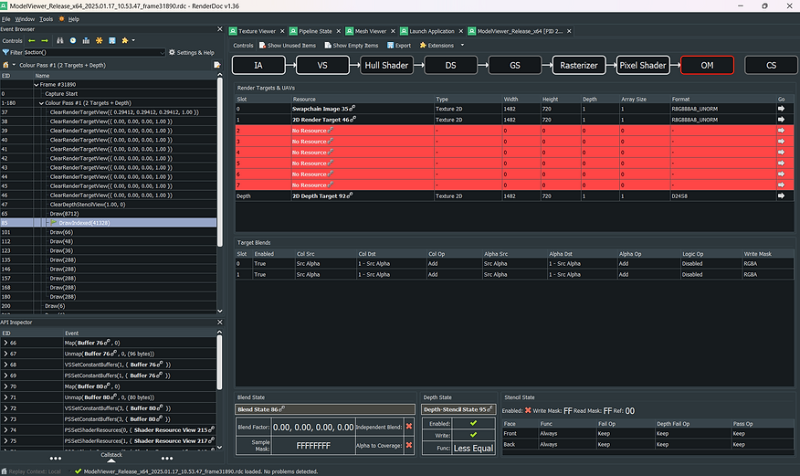
No resources bound on the given slots
Output Merger stage for the above capture
-
Learned how to read the mesh input data, output data and how it looks visually

Buffer data sent to GPU
Output data in NDC space
Input data in local space visualized
Input vertex data that it sent to the GPU

Output data in NDC space visualized
Output vertex data finally rendered on screen
-
Learned how to debug shaders (can only be done in Debug configuartion)
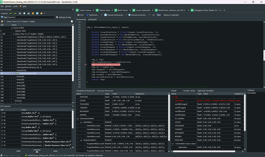
Stepping through vertex shader when debugging
Input data and constants sent to vertex shader
Output data
Debugging data in vertex shader

Stepping through pixel shader when debugging
Input data and constants sent to pixel shader
Output data
Debugging data in pixel shader